PicoSapien: Part 1 - Proof of Concept and Getting Started
9/18/2024, 3:42:50 AM
A Flea Market Find
This past Saturday, I ended up at a local flea market and found this little guy. It's a RoboSapien V1 from 2004.
I had never had one, but I had always seen the TV commercials and wanted one. This was my chance.
It did not come with the remote, so I wondered if I could control it with a Raspberry Pi Pico.
I decided it was worth it, and it gave me something to tinker with.

I thought the Pico would have to drive each motor and connect directly to each sensor until I found this great article. It turns out I could solder a wire directly to the pad on the PCB that connected to the IR sensor and send simulated IR signals! The article used a RaspBerry Pi Zero, and I have one. But I was really wanting to use a Pico and Rust 🦀.
Tear down
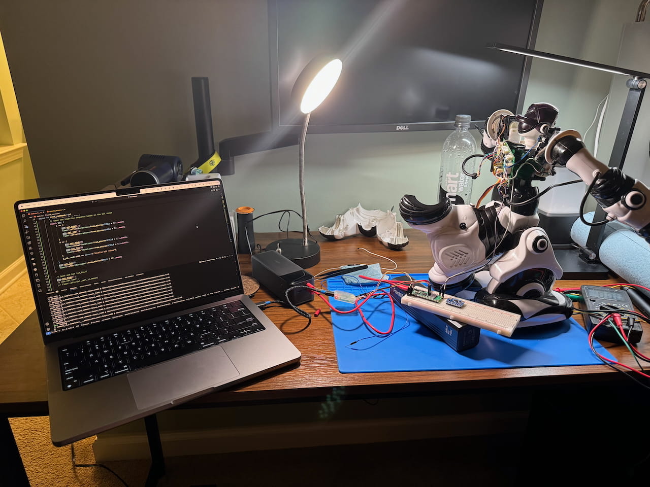
Before I could start coding, I wanted to get a teardown and solder a wire to the connection pad. The PCB I needed was inside the chest cavity. Here's a picture of the front of the board once I took the chest plate off.

Once I removed the board, I soldered the white wire to the top pad labeled OUT and to the right of VRE. This pad is connected to the white wire on the wire harness that goes to the head of the Robot, which houses the IR sensor. I also soldered a ground wire to a pad marked ground on the bottom right for when I mount the Pico. I also plan on getting the 3.3v to run the pico from the Robot, but I will cover that later once the prototyping is finished.

** You can put a couple of jumper wires in the Robot's head wire harness to get a proof of concept without removing the board. I had trouble with this, but I think some of my earlier code was to blame. The IR OUTout is the white wire, and the ground is the grey wire in the harness. In the picture below can see the top wire harness is labeled as HEAD.

How To Simulate Controller Commands
The RoboSapien was originally meant to be controlled by this remote.

The remote works just like a TV remote via IR (infrared). Point at the head of the robot that houses the receiver and press a button, and the robot will go off. I did not know IR works by sending pulses of light containing binary commands. The signals are then translated into electrical signals sent to the controlling chip. Just like what we use in GPIO pins in microcontrollers!
The article listed before goes into a much deeper dive of content, and 100% recommend giving it a read because none of this project, would not be possible without its creator. Also worth nothing all the following information and graphics are the original content, of the article and all credit goes to them.
Pulses on the GPIO pin carry out the commands. Set the pin to be high for x amount of time, then low for y amount of time, and you can send binary code to the chip controlling the robot. Following this link, you can see the below description of how the pulses should be timed and a list of commands.
Timing based on 1/1200 second clock (~.833ms)
Signal is normally high (idle, no IR).
Start: signal goes low for 8/1200 sec.
Data bits: for each of 8 data bits, space encoded signal depending on bit value
    Sends the most significant data bit first
    If the data bit is 0: signal goes high for 1/1200 sec, and low for 1/1200 sec.
    If the data bit is 1: signal goes high for 4/1200 sec, and low for 1/1200 sec.
    BTW: The first bit (msb) is always 1 (valid codes are from $80 to $FF)
When completed, signal goes high again.
No explicit stop bit. Minimal between signals is not known.
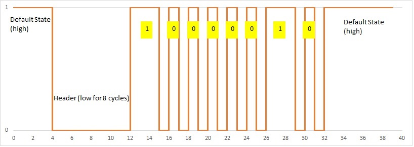
Another way to break that down is. When the program starts, set the GPIO pin as high and keep it high; this is the default state.
Then, set the pin as low for 8 cycles of .833ms (a total of 6.664 microseconds).
That is telling the robot you are about to send a command. Then, send the binary command. 1's are highs, and 0's are lows.
We are going to use the 0x82 command that tells the robot to put its right arm out as an example.
This would be sent over as 1000 0010 (all commands start with a 1 or high and are 8 bits long).
So if the bit is a 1, the pin is set as high for 4 cycles of .833ms(3.332 ms),
then set low for 1 cycle of .833ms to signify the bit is a 1. If the bit is 0, the pin is low for 1 cycle of .833ms.
After you send the bit, you always return to high(default) before processing the next bit.
Once you are done with the command, set the pin back to high to signify it is done being transmitted.
A great visualization done in the original article.
** I found the commands would work better if the pico was already on and had the pin high before turning on the robot during POC.
Getting It To Work With Rust And The Pico

The examples in the previous article were all done on a Raspberry Pi Zero using Pigpio. But I want to use a Pico and Rust, more specifically embassy_rp, my current go-to crate for writing any code for the Pico. The code is nothing to write home about, but it gets the job done for a proof of concept! I just took the explanation from the previous articles, set it high or low, and waited the time. You can find the code below with some explanations.
#![no_std]
#![no_main]

use commands::RobotCommand;
use defmt::*;
use embassy_executor::Spawner;
use embassy_rp::gpio::{Level, Output};
use embassy_time::{Duration, Timer};
use {defmt_rtt as _, panic_probe as _};

const CYCLE: u64 = 833;

async fn send_command<'a>(pin: &mut Output<'a>, command: u8) {
    // Pin is set to high and when low for 8 cycles it signifies a start of a command
    pin.set_low();
    Timer::after(Duration::from_micros(CYCLE * 8)).await;

    //Convert the command to the 8 bit binary representation
    for i in (0..8).rev() {
        let bit = (command >> i) & 1;
        // Send the high-low sequence based on the bit value
        match bit {
            1 => {
                pin.set_high();
                Timer::after(Duration::from_micros(CYCLE * 4)).await;
                pin.set_low();
                Timer::after(Duration::from_micros(CYCLE * 1)).await;
            }
            0 => {
                pin.set_high();
                Timer::after(Duration::from_micros(CYCLE * 1)).await;
                pin.set_low();
                Timer::after(Duration::from_micros(CYCLE * 1)).await;
            }
            2_u8..=u8::MAX => error!("Invalid bit value"),
        }
    }

    // Set back to high to end the transmission (default)
    pin.set_high();
}

#[embassy_executor::main]
async fn main(_spawner: Spawner) {
    let p = embassy_rp::init(Default::default());
    let delay = Duration::from_secs(15);
    //This is the pin that the white wire is connected to
    let mut pin = Output::new(p.PIN_16, Level::High);

    //The pin is default as high
    pin.set_high();

    loop {
        //Sends a command to tilt left
        send_command(&mut pin, 0x8B).await;
        Timer::after(Duration::from_secs(3)).await;
        //Sends a command to tilt right
        send_command(&mut pin, 0x83).await;
        Timer::after(delay).await;
    }
}
Then below can see a video of it's output and my POC setup!
That wraps up part one! If you have made it this far, thanks for reading! I have some future plans. I'm mostly finishing out the Pico software to receive commands via a web socket, then creating a web app to send commands and be used as a controller. So stay tuned for those updates!
Till the next post check out some videos of the commands!
This is a command to pick up objects with the right arm 0xA4
A neat Citizen Kane reference for a power off command 0xD1!